Figuring Speed and Feeds for a Drill
The SpeeDoctor Our "Smart" Feed and Speeds wizard will recommend the best cutting speed, feed rate, and carbide grades for Milling, Turning, Drilling and Grooving (based on more than 50 parameters)
How to use the SpeeDoctor (speed and feed calculator)
- General
- Initial Screen (Page 1)
- Raw material selection (Page 2)
- Main Parameters (Page 3)
- Additional Parameters (Page 4)
- Calculation Parameters (Page 5)
- Results (Page 6)
- Speeds and Feeds: Terms Glossary
General
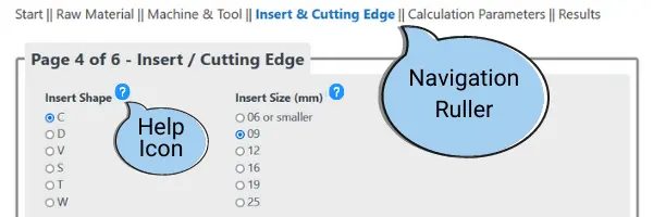
- On the top of the Speeds and Feeds Calculator, you will find the "Navigation Pane".
- You can use it to Jump directly between the different pages of the calculator.
- Near many of the fields(Where it is needed), there is a "Help Icon". If you click it, a help box for that specific field will pop up.
- Fields with a Light Yellow Background are calculated result fields that you cannot edit.
Initial Screen (Page 1)
Make sure to choose the correct Unit, Application, and Material Group on the initial page since the following pages of the Speed and Feed calculator will depend on these choices!
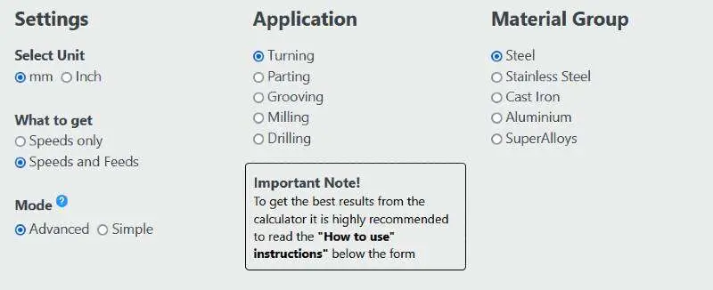
- For grooving application – Choose grooving for shallow grooving and parting for deep grooving.
- What to Get: If you need only the cutting speed [1] , select "Speeds Only", and you will be asked to enter fewer parameters.
- Mode – Advanced / Simple: In simple mode, you need to enter fewer parameters, and the calculator will rely on the system defaults. In advanced mode, you can control all the parameters and get more accurate Feeds and Speeds. On Mobile devices, the Simple mode is automatically activated.
- Units: Selecting Inch will display speeds in SFM and feeds in IPR [2] .
Raw material selection (Page 2)
The raw material is a primary factor in cutting speed calculations. Precise raw material selection will enhance the accuracy of the results. Give it proper attention!
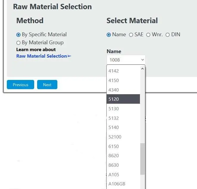
- Always start with Trying to find your material in the list of the "By specific Material" option.
- If you don't find the exact material, but you find it near equivalent, choose it.
- If you cannot find a near alternative, switch to the "By material Group [3] " option.
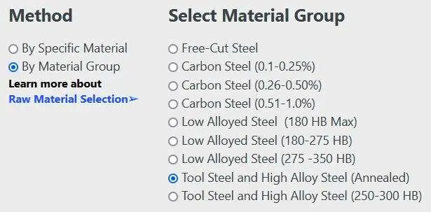
- Choose the correct material group.
- If you are unsure, you can try to find it in our Material Groups Table
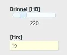
- If the selected group or material is "hardness [14] sensitive", the system will display a hardness slider.
- If you are not sure what is your material's hardness, stay with the default value.
- However, if you know (or can find out) the actual hardness, adjust the slider accordingly. Hardness has a significant influence on Speeds and feeds, and setting the correct hardness increases the accuracy of the results!
Main Parameters (Page 3)
This screen has different fields depending on the leading application you chose in the initial screen.
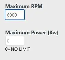
- For all applications, you can set the Machine's maximum RPM [15] and Power limits. By default, the maximum RPM for lathe machines is 6000 and for milling machines 15,000. Power is not limited unless you set a value.
Turning and Grooving specific parameters
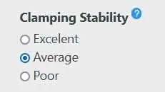
- Clamping Stability: Try to estimate the overall combined stability of your tool and workpiece. If you are unsure, leave it as "average".
- Excellent: The workpiece is firmly clamped and supported and the tool is firmly clamped with a short overhang.
- Poor: The workpiece L/D factor is large (Long shafts) without a steady rest (Luneta) and/or tailstock and/or the tool has a long overhang.
- Average: Something in the middle.
- The stability factor will affect mainly the speed calculations and by to a lesser extent the feed calculations.
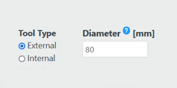
- Tool Type: Externa or Internal.
- Workpiece Diameter: Enter the minimum diameter in your operation. Please pay attention that the minimum diameter is the final machined diameter for external operations, but it is the initial diameter in internal operations.
- This parameter will influence the RPM and is important for small diameters, as it may set an upper limit for the calculation of the cutting speed.
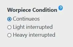
- Workpiece Condition:
- Continuous – For typical workpiece with no interruption.
- Heavy interrupted – For slotted workpiece / Square workpiece / etc.
- Light interrupted – For round workpiece with interference such as significant runout, scale, pits, etc.
- The factor will affect mainly the speed calculations and by to a lesser extent the feed calculations.
Parting off specific parameters
- Clamping stability and Workpiece condition: See the explanations in the above Turning and grooving section.
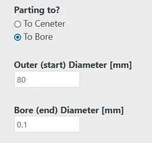
- Parting to the center or into a bore.
- The default is parting to the ceneter.
- When you select "To Bore", a new field will appear to enter the bore diameter.
Milling specific parameters
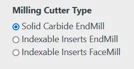
The Milling Speeds and Feed Calculator supports the three main types of milling cutters:
- Solid Carbide EndMills: 90° Endmills, Ballnose Endmills and Chamfaring Endmills.
- EndMills With Indeaxable Inserts: 90° Endmills, Ballnose Endmills, Chamfaring Endmills and Endmills with round inserts.
- FaceMills With Indeaxable Inserts: 90° Facemills, Fast-Feed Facemills, 45° Facemills mills and Facemills with round inserts.
In total, the calculator handles 11 different Milling Cutter configurations!
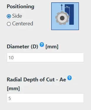
The Basic Milling Parameters that are needed for all the different configurations:
- Milling Cutter Position: How is the cutter positioned relative to the milling operation.
- Diameter: Eneter the Miiling Cutter Diameter. (The largest diameter in case of non 90° cutters)
- Radial Depth of Cut [4] : The radial depth of cut is a critical paramter for reliable speed and feed calculatins! It affect dramaticly both the feed (Due to chip thinning [5] ), and the cutting speed (Due to the amount of time each teeth "spends" outside the material.

- Clamping Stability: Try to estimate the overall combined stability of your tool and workpiece. If you are unsure, leave it as "average".
- Excellent: The workpiece is firmly clamped and the tool is firmly clamped with a short overhang.
- Poor: The workpiece is poorly clamped or has thin walls, or the tool has a long overhang.
- Average: Something in the middle.
- The stability factor will affect mainly the speed calculations and by to a lesser extent the feed calculations.
Drilling specific parameters
- Clamping Stability: See the explanations in the above Milling section.
- Basic cutter parameters: Type, Diameter, and Number of flutes
Additional Parameters (Page 4)
The data entered on this page is not needed for cutting speed calculations. If "Speed only" is selected on page 1, the Feeds and Speeds Calculator will skip directly from page 3 to page 5.
Turning Inserts definition
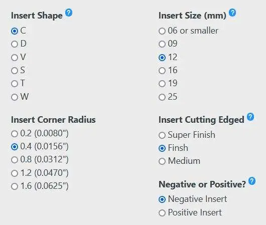
- Shape, Size, and Radius are selected according to the ISO standard, depending on the unit you chose in the initial screen. A good dictionary can be found here.
- The IC value is calculated and shown for information only.
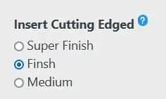
- Classify the cutting edge [6] geometry of the insert you plan to use.
- The best method is to check in the supplier's catalog how he classifies it.
- If this information is not available use your best judgment or leave the default system value.
Parting-off Insert Definition

- Choose with the sliders the Insert width and frontal angle.
- The default frontal angle is 0 (Straight edge insert).
- Classify the chip breaker/cutting edge geometry of the insert you plan to use.
- The best method is to check in the supplier's catalog how he classifies it.
- If this information is not available use your best judgment or leave the default system value.
Grooving Insert Definition

- Choose with the sliders the Insert width and corner radius.
- Classify the chip breaker/cutting edge geometry of the insert you plan to use.
- The best method is to check in the supplier's catalog how he classifies it.
- If this information is not available use your best judgment or leave the default system value.
Milling Cutter Parameters
Depending on the main type of cutter you selected on page four, The calculator will present you with the relevant Sub-Types. In total, the Milling Speeds and Feeds Calculator support 11 configurations!
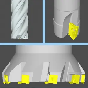
Solid Carbide EndMills:
- 90° Solid Carbide.
- BallNose Solid Carbide.
- Chamfaring Solid Carbide
Indexable Inserts EndMills:
- 90° Endmills.
- BallNose Endmills.
- Chamfaring Endmills.
- Endmills with Round Inserts.
Face Mills:
- 90° Facemilss.
- 45° Facemills.
- Facemills with Round Inserts
- Fast-Feed Facemills.
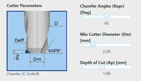
According to the Sub_type selected, The system will present the relevant sketch with its parameters, such as Axial Depth of Cut [7] (As an example, we show here the parameters for a Solid Carbide Chamfering Endmill). The Effective Diameter will be calculated accordingly.
Calculation Parameters (Page 5)
You can customize how the Speed and Feed Calculator determines the cutting data and get results that are better tuned for your specific application. You can also hit "Next," and the calculator will apply the default values. in "Simple Mode" and mobile devices this screen is ignored.
Calculation Mode – Customize the relationship between Carbide Grades recommendation and Cutting Speed calculations

- "Get Cutting Conditions And Best Grades [16] ": This is the default mode. In this mode, the calculator will first determine the ideal grade parameters and list the leading carbide suppliers' most suitable grades accordingly. Each grade gets a score between 0 and 100 that estimates "how close" the grade is to the "ideal grade".
- "Provide A Grade And Get Cutting Conditions": Additional fields are displayed on the right-hand side in this mode. You can specify the grade you are planning to use, and the system will calculate the cutting conditions according to your chosen grade. Besides, it will give your grade a score between 0 and 100. This score estimates "how close" is your selected grade to the "ideal grade". The grade list that appears at the bottom of the results page shows the "closest" grade from each leading brand to your grade. The system looks only at the grades that each brand recommends to the application and tries to determine which one best resembles your selected grade. Each grade in the list gets a score that estimates how it compares with your selected grade.
Speed Control (All Applicatiuons) – Customize how the Speeds and Feeds Calculator fine-tunes the Cutting Speed
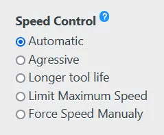
- Automatic – The system's default. The calculator will estimate a good balance between productivity (higher cutting speed) and tool-life (lower cutting speed).
- Aggressive – The calculator estimates the highest cutting speed that the insert can handle at the expense of lower tool life.
- Longer Tool LIfelife – The calculator will provide a medium cutting speed that will give a longer insert tool-life.
- Limit maximum speed – You can set an upper limit that the system will not exceed (even if, according to the algorithm, a higher speed can be used). The carbide grade recommendations will be adjusted accordingly.
- Force Speed Manually – If you know you will use a specific speed, you can type it in. It is useful when you only want to get recommendations for the best grade and feed rate.
Feed Control (Turning, Parting and Grooving) – Customize how the Feeds and Speeds Calculator fine-tunes the Feedrate
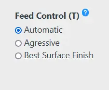
- Automatic – The system's default. The calculator will estimate a good balance between productivity (higher Feedrate [8] ) and Surface Quality (lower Feedrate). Note: The surface quality is proportional to f2
- Aggressive – The calculator estimates the highest feedrate that the insert can handle at the expense of worse surface quality.
- Best Surface Finish [9] – The calculator will provide the minimum possible feed rate to get good surface finish.
Feed Control (Milling) – Customize how the Feeds and Speeds Calculator fine-tunes the Chip Load and Table Feed
The Chip Load [17] (Maximum chip thickness), is the largest chip that a cutting edge can handle without breaking and still maintain decent tool-life. In the case of 90° cutters taking a radial depth of more than 50% of the cutter's diameter, the chip load is exactly the Feed per Tooth [10] . However, when the radial depth gets smaller, and the cutter is not a 90° shape, you can dramatically increase the feed without getting above the allowed Chip Load. The Milling Speed and Feed Calculator automatically calculated the right feed to keep the desired chip load. The calculator works in two stages:
- Stage 1 – The system calculates the desired maximum chip load according to the cutter type, diameter and raw material. You have the below options to control how the chip load is calculated.
- Automatic – The system's default. The calculator will estimate a good balance between productivity (bigger Chip Load) and proces securty.
- Aggressive – Larger chip load, but a less secure proces.
- Low – Very secured proces at the expense of a smaller Chip Load.
- Manual – Most tool suppliers list in their catalogs the recomned chip load for their product. You can eneter this value instead. This is the most recomended method if you have this data availble.
- Stage 2 – Based on the Chip Load calculated in Stage 1, the system will calculate the correct feed to maintain the chip-load. Three se[erate factros are evaluated to reach the correct result. You can "tell" the calculator which methods to use. (we recomend to leave the system defaults).
- Radial Chip Thinning– This enhancmentis based on the relation between the radial depth of cut (Ae) and the cutter effetive diameter (Deff).
- Entry Angle [11] Chip Thinning– This Enhancemnt is based on the Entry Angle (KAPR) of the the cutting edge and/or the cutting edges radius.
- Circular Interpolation– If the cut is not along a straight line turn on also this option.
Results (Page 6)
The Calculator divides the results into 3 sections. The main results are the cutting speed and feedrate, secondary results such as power consumption and operation time, and carbide grades recommendations.
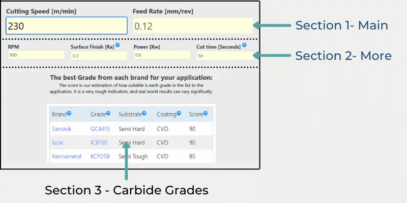
- Section 1 – Main parameters: Cutting speed, feedrate, spindle speed and table feed [12] .
- Section 2 -Secondary parameters: Additional cutting data that is calculated based on the speeds and feeds.
- Surface Roughness (Turning Only): The theoretical surface finish is based on corner radius and feedrate.
- Machining Power (All Applications): Based on raw material and MRR [13] .
- Metal Removal Rate (All Applications): Based on cutting data and tool geometry.
- Cut Time (All Applications): Given for a nominal distance (100 mm or 4″ for turning, 10 mm or 3/8″ for grooving, etc.)
- RPM "Clamped" diameter: When performing operations that involve a significant change in diameter such as parting off, deep grooving, and face turning, in many cases, the cutting speed is forced by the maximum allowed RPM at a specific diameter. This diameter is called the "clamp" diameter. In these cases, the calculator will display two additional result fields:
- RPM diameter – The diameter where the cutting speed requires the spindle to rotate at the maximum allowed speed. Below this diameter, the cutting speed gradually decreases, and the RPM stays constant.
- Full speed cut – The calculated displays the percentage of time operated with the calculated cutting speed before it is "clamped" by the RPM.
- Section 3 – Carbide Grades
- Grade recommendation is available for all applications except drills and solid carbide endmills.
- By default, the Speed and Feed Calculator lists one grade per each major carbide manufacturer that it estimates as the best fit for the given parameters. Each grade gets a score between 0 and 100 that indicates how suitable it is. Keep in mind that these estimations cannot be accurate, and there is no guarantee that the actual results will not be different.
- When the "Provide A Grade And Get Cutting Conditions" is selected, the calculator lists.
Speeds and Feeds: Terms Glossary
Explanation of all the technical terms that are used in the Speeds and Feeds Calculator
Source: https://www.machiningdoctor.com/calculators/speeds-and-feeds-calculator/
0 Response to "Figuring Speed and Feeds for a Drill"
Post a Comment